Switching and VLAN (Virtual LAN)
What is Switch?
Switch is a networking device used for the interconnection of devices within the same network. Switches are generally Layer 2 devices. Nowadays, Layer 3 switches are also available.
Router vs Switch
A router is a layer 3 networking device used for the interconnection of different networks. Switch is used for the interconnection of devices within the same network. In a large network like an office or school, each and every device are connected to a switch which are collectively connected to a single router.
In fig 1, the switch is used for the interconnection of the two hosts—Win and Ubuntu CLI. They are collectively connected to the router which further grants the access to the internet.
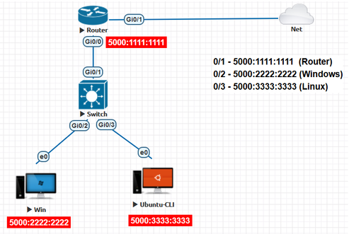
Fig 1. Basic switch layout with internet connection
Unlike routers, switches do not work on the basis of the IP address. Since they are layer 2 devices, they work on MAC address. MAC address is also known as Physical address or Layer 2 address. In the fig 1, When a packet is sent from the Windows machine to the Linux machine, the source MAC address will be 5000:2222:2222 and the destination MAC address will be 5000:3333:3333. Switches are available with many interfaces and the administrator can pick a switch according to the number of end devices that he has to connect to the internet. The maximum number of ports available in a switch are 48. If the number of end devices exceeds this count, the administrator can choose to opt a 2-tier or a 3-tier switch network architecture. Below Fig 2 shows a 2-tier switch network having core and distribution layer of switches. Similarly the 3-tier network design consists of a core, distribution and access layer of switches. Furthermore these designs eliminate single points of failure thus improving overall throughput.
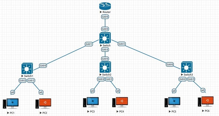
Fig 2. A 2-layer switch
MAC address table
Switches store the MAC address of all the hosts connected to them mapped to the corresponding interface in which they are connected. This is called MAC table or CAM (content access memory) table. Whenever the switch receives any kind of traffic like ARP, DHCP, Broadcast etc, it will update the MAC address table using the source MAC address in that traffic. In every frame that the PC sends, source MAC address does not change. Switch reads the source MAC address from the frame header and updates its MAC table.
Fig 3 shows the MAC table of the switch shown in fig 1 when the PCs and router are not turned on.
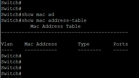
Fig 3. MAC table of a switch at the initial setup
When the PCs and router in the fig 1 are turned on, they start sending packets from which switch updates the MAC table as given in fig 4. Fig 4 shows four columns. Column 1 shows VLAN. The concept of VLAN will be discussed later. By default, all the interfaces belong to VLAN 1. The MAC address column displays the MAC address of the device connected to the switch. Type column describes the mode by which the MAC table was updated. The table was updated dynamically when there is a flow of data. It was not updated manually by hardcoding the MAC address which is called static type. Unlike hubs, switches forward the packets to the destination host alone. The MAC address table is responsible for this. Only when the MAC address table has no entry about the destination host, the packet gets forwarded to all the interfaces. Also, the entries in the MAC table stay for a period of 300 seconds from the last data received from the corresponding host. If there is no flow of packet for more than 300 seconds, then the corresponding entry gets removed automatically as shown in fig 5.
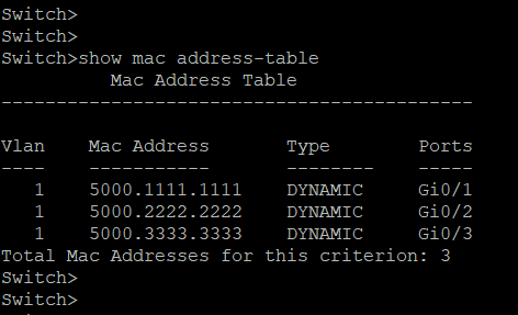
Fig 4. Updated MAC table for the layout in fig 1.
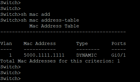
Fig 5. MAC table for the layout in fig 1 when the Windows and Linux systems are idle for more than 300 seconds.
The command for viewing the MAC address table in a cisco switch is
Switch>show mac address-table
Fig. 6, shows the connection between two switches- switch 1 and switch 2 with the hosts connected to them and their corresponding IP address and MAC address. The MAC table of the switch 1 will have all the entries of its directly connected hosts and the corresponding interface such as 5000.2222.2222 → 0/1; 5000.3333.3333 → 0/2. MAC table will be filled up in a similar way for switch 2 with 5000.4444.4444 → 0/1 ; 5000.5555.5555 → 0/2.
When the devices in the topology is turned on, protocols like ARP and DHCP initiates packets that are sent through these switches. These protocols rely on broadcast for their basic function. When switch 1 receives these broadcast, they in turn continue to broadcast them also they learn the source MAC address from the broadcast frame. Thus Switch 1 will then learn MAC address of PC3 and PC4 which are directly connected to switch 2 and maps to the port 0/3 (of switch 1) through which the broadcast arrived. Similarly switch 2 will learn source MAC address of PC1 and PC2 which are directly connected to switch 1 through these broadcast frames sent by the protocols and maps to its interface 0/3 (of switch 2).
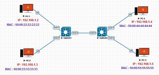
Fig 6. Connection between two switches.
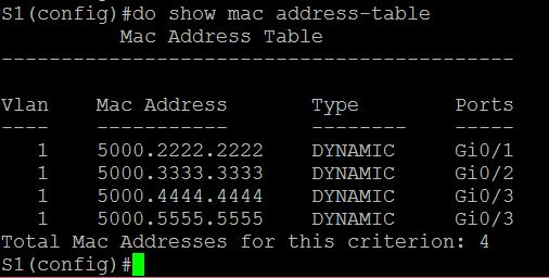
Fig 7. MAC address table of Switch 1.
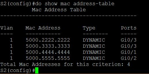
Fig 8. MAC address table of Switch 2.
3 - Tier architecture
In a large organization, the architecture generally used is 3 tier architecture. Consider an example, if an organization has as large as 2000 hosts/PCs to connect. A switch can have a maximum of 52 ports. In this case, a single switch cannot serve the purpose.
In 3-Tier architecture, three different layers of switch are used. The router is connected to the switch in tier 1 which is also known as Core switch. The tier-2 extends the core switch. The switches in tier-2 are known as Distribution switch. The distribution switch is further extended by tier-3 switches known as Access switch. If the number of hosts are large, then 3-tier is required. If not, 2-tier is enough with only Core and Distribution switches.
The maximum number of switches recommended between the router and the host is 3. If it exceeds 3, then there might be packet loss. Also, the maximum number of entries in a traditional MAC address table is approximately 65000.
Virtual LAN
The basic idea of VLAN is splitting a single switch into many individual separate switches logically. The word logically accounts for the virtual part in VLAN. To understand the use case of a VLAN, let us see an example. If in an organization there are three different departments, namely HR, accounts and admin. Assume that all the departments are in the same network. Each department with different access restrictions. Assume that HR is allowed to only Gmail, Accounts department is allowed to visit only banking websites and the Admin can visit any website. In this environment, the restrictions can be done by Access Control List (ACL) but it is not the efficient strategy because DHCP does not allocate the same IP address to a host every time. Therefore, VLAN is the ideal solution. Fig. 9 shows the connection of 6 hosts to a switch. With respect to the above example, assume that devices, 1.2 and 1.3 belong to the Admin department which are in the 1.0 network, 2.2 and 2.3 belong to the Accounts department which are in the 2.0 network and 3.2 and 3.3 belong to the HR department which are in the 3.0 network.
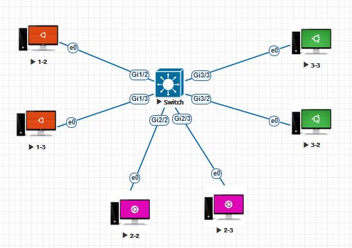
Fig 9. VLAN architecture
Here, though all the hosts are connected to the same switch, they can be logically separated into three different switches. That is, each of them configured in a separate VLAN. In this case, the interfaces Gi1/2 and Gi1/3 belong to the same VLAN, say VLAN 10. The interfaces Gi2/2 and Gi2/3 belong to the same VLAN, say VLAN 20. The interfaces Gi3/2 and Gi3/3 belong to the same VLAN, say VLAN 30. Now, the transmission can take place only between the same VLANs. Therefore, attaining both maximum security and efficiency. The logical connection of VLAN configuration in fig. 9 network is represented in the fig. 10.
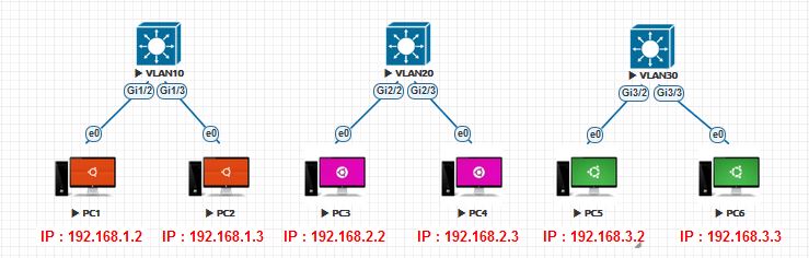
Fig 10. Logical VLAN architecture
Switch1>en
Switch1#configure terminal
Switch1(config)#vlan 10
Switch1(config-vlan)#name admin
Switch1(config-vlan)#vlan 20
Switch1(config-vlan)#name accounts
Switch1(config-vlan)#vlan 30
Switch1(config-vlan)#name hr
Switch1(config-vlan)#exit
Switch1(config-if)#int g1/2
Switch1(config-if)#Switch1port access vlan 10
Switch1(config-if)#int g1/3
Switch1(config-if)#Switch1port access vlan 10
Switch1(config-if)#int g2/2
Switch1(config-if)#Switch1port access vlan 20
Switch1(config-if)#int g2/3
Switch1(config-if)#Switch1port access vlan 20
Switch1(config-if)#int g3/2
Switch1(config-if)#Switch1port access vlan 30
Switch1(config-if)#int g3/3
Switch1(config-if)#Switch1port access vlan 30
Switch1(config-if)#exit
Trunk Interface
One of the common terms associated with VLAN is trunk port. The use of trunk port will be explained below. Consider the configuration in fig. 11. As we already know that the flow of packets can take place between the hosts in the same VLAN only, if there are many hosts and they are ought to be in the same network, then using 2 or more switches to form a single network is the ideal solution.
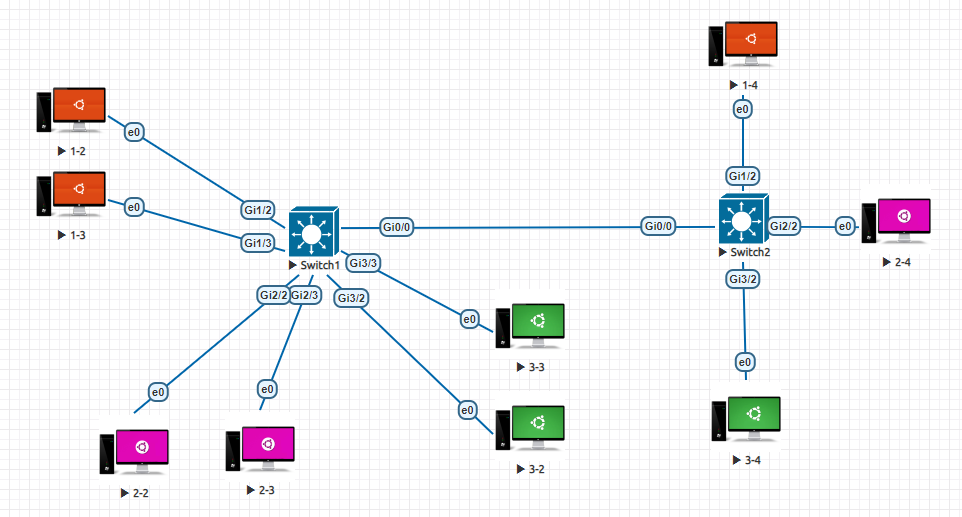
Fig 11. Interconnection of two switches using trunk port
In the above figure, the switch 1 has 1.2 & 1.3 in VLAN 10, 2.2 & 2.3 in VLAN 20 and 3.2 & 3.3 in VLAN 30. This switch is connected to another switch say, switch 2 with hosts 1.4 in VLAN 10, 2.4 in VLAN 20 and 3.4 in VLAN 30. Since all the hosts in switch 1 and switch 2 belong to either of the three VLANs the host 1.2 should be able to reach 1.4. The output is shown below in fig. 12.
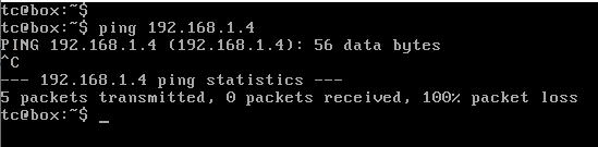
Fig 12. Ping request without trunk port configuration
The above figure shows that the ping is unsuccessful. This is because though the two hosts are in the same VLAN, the interface connecting them, i.e. Gi0/0 of the two switches are not configured. Therefore, they are in default VLAN which is VLAN 1. If these two interfaces are configured as VLAN 10, then the host 1.2 and 1.3 can reach 1.4 but the hosts 2.2, 2.3, 3.2 and 3.4 cannot reach 2.4 and 3.4 respectively. This is the use case of trunk port configuration. Here, if the interfaces Gi0/0 are configured as trunk port, then this would allow all the packets irrespective of the VLAN. Therefore, all the hosts in switch 1 can reach the hosts in switch 2 which are in the same VLAN. During port configuration if either of the interface is configured for the trunk mode, then the other interface also automatically detects the trunk port configuration and gets configured.
The command for configuring trunk port in a cisco switch is
Switch2>en
Switch2#configure terminal
Switch2(config)#vlan 10
Switch2(config-vlan)#name admin
Switch2(config-vlan)#vlan 20
Switch2(config-vlan)#name accounts
Switch2(config-vlan)#vlan 30
Switch2(config-vlan)#name hr
Switch2(config-vlan)#exit
Switch2(config-if)#int g1/2
Switch2(config-if)#Switch2port access vlan 10
Switch2(config-if)#int g2/2
Switch2(config-if)#Switch2port access vlan 20
Switch2(config-if)#int g3/2
Switch2(config-if)#Switch2port access vlan 30
Switch2(config-if)#exit
Switch2(config)#int g0/0
Switch2(config-if)#switchport trunk encapsulation dot1q
Switch2(config-if)#switchport mode trunk
Switch2(config-if)#exit
The ping request from 1.2 to 1.4 after the trunk port configuration is given below.
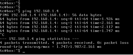
Fig 13. Ping request with trunk port configuration
Consider the topology given in fig. 14. If the ping request is from 192.168.1.2 to 192.168.2.3, there will not be any packet transfer as shown in fig. 15. This is because the switch to router interfaces (Gi1/1, Gi2/1 and Gi3/1) are not configured with the appropriate VLAN (Interfaces are in default VLAN 1).
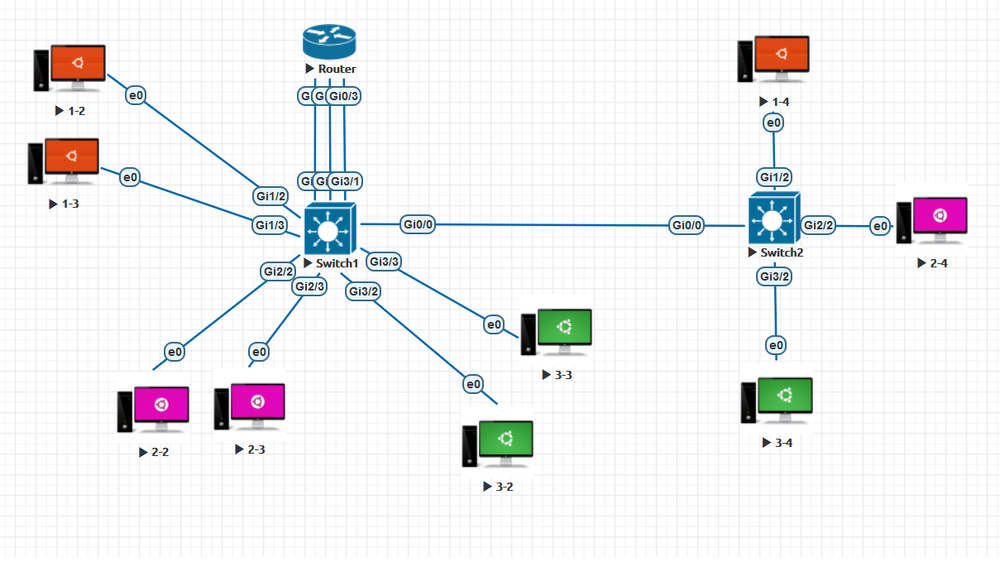
Fig 14. VLAN configuration between switches with a router
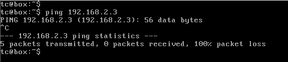
Fig 15. Ping result without configuring switch-router interface with VLAN
Therefore, these interfaces have to be configured with the appropriate VLAN for the interconnection of hosts in different network to be successful. Thus, configuring the interface Gi1/1 with VLAN 10, Gi2/1 with VLAN 20 and Gi3/1 with VLAN 30. Also, the interface of the router Gi0/1, Gi0/2 and Gi0/3 has to be configured with the respective network Gateway address, i.e. 192.168.1.1, 192.168.2.1 and 192.168.3.1. Now, initiating a ping request from 192.168.1.2 to 192.168.2.3, we get the result as shown in fig. 16 and the VLAN briefing of the switch is shown in fig. 17.
The command for configuring the switch-router interface is
Switch1>enable
Switch1#configure terminal
Switch1(config)#int g1/1
Switch1(config-if)#switchport access vlan 10
Switch1(config-if)#exit
Switch1(config)#int g2/1
Switch1(config-if)#switchport access vlan 20
Switch1(config-if)#exit
Switch1(config)#int g3/1
Switch1(config-if)#switchport access vlan 30
Switch1(config-if)#exit
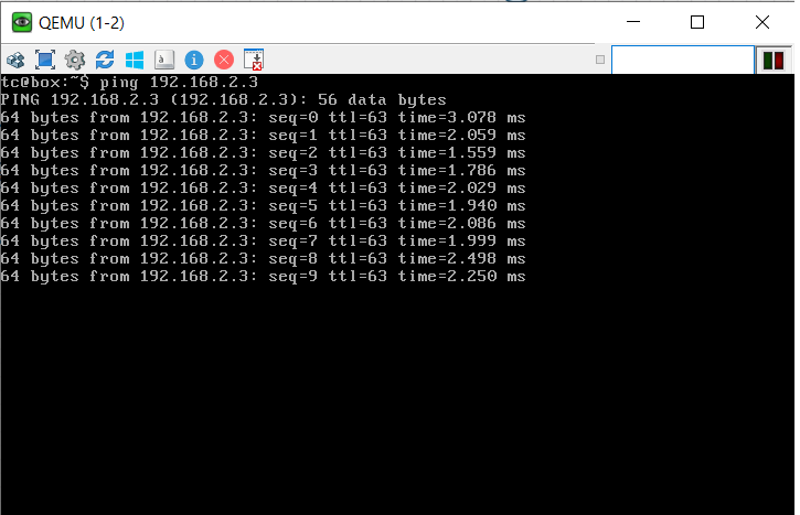
Fig 16. Ping result after configuring switch-router interface with VLAN
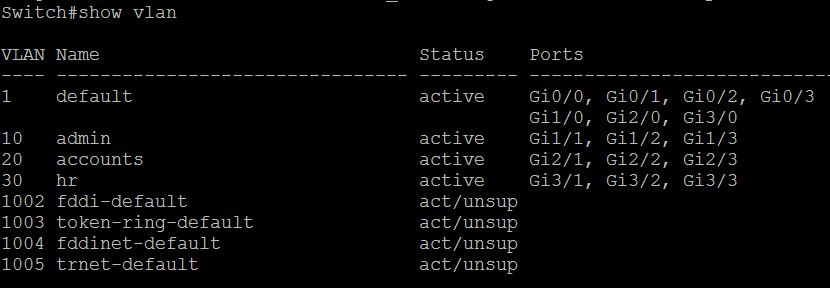
Fig 17. VLAN briefing of the switch
Now, with the above configuration and topology the hosts from one network can reach the hosts in different networks.
Router-on-a-stick
The above topology seems good for a small network. But, on noticing further it is evident that for each VLAN we require one interface of the router. In a typical network, there would be many VLANs. Each of them cannot be provided with a unique interface. Therefore, to solve this problem we come up with the concept called Router on a Stick or Sub interface. Here, we use a single interface of the router and split it into many sub interfaces each for one VLAN. By this method, the network becomes more cost efficient. The schematic of the Router on a Stick is shown in fig. 18.
In the figure, the interface Gi0/0 of the router is split into sub interfaces Gi0/0.10 and Gi0/0.20
Then, IP address is assigned to the two sub interfaces and the interface is configured with dot1q encapsulation and the respective VLAN number for each interface. That is, interface Gi0/0.10 with VLAN 10 and Gi0/0.20 with VLAN 20 or vice-versa.
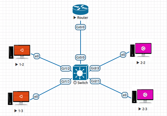
Fig 18. Router on a Stick topology
The interface briefing of the router in the above topology is given below in the fig. 19.
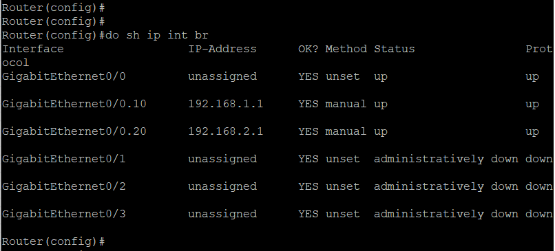
Fig 19. Interface details of the router after configuring Router-on-a-stick
Switch>en
Switch#configure terminal
Switch(config)#vlan 10
Switch(config-vlan)#name admin
Switch(config-vlan)#vlan 20
Switch(config-vlan)#name accounts
Switch(config-vlan)#exit
Switch(config-if)#int g1/2
Switch(config-if)#Switchport access vlan 10
Switch(config-if)#int g1/3
Switch(config-if)#Switchport access vlan 10
Switch(config-if)#int g2/2
Switch(config-if)#Switchport access vlan 20
Switch(config-if)#int g2/3
Switch(config-if)#Switchport access vlan 20
Switch(config-if)#exit
Switch(config)#int g0/0
Switch(config-if)#switchport trunk encapsulation dot1q
Switch(config-if)#switchport mode trunk
Switch(config-if)#exit
Commands to configure Router in a Router-On-a-Stick Topology
Router>enable
Router#configure terminal
Router(config)#int g0/0
Router(config-if)#no shut
Router(config-if)#exit
Router(config)#int g0/0.10
Router(config-subif)#encapsulation dot1Q 10
Router(config-subif)#ip address 192.168.1.1 255.255.255.0
Router(config-subif)#exit
Router(config)#int g0/0.20
Router(config-subif)#encapsulation dot1Q 20
Router(config-subif)#ip address 192.168.2.1 255.255.255.0
Router(config-subif)#exit